Page 1 of 4
Dreamdisk lives!
Posted: Sun Mar 24, 2024 5:37 pm
by jltursan
Well, after quite some work and a couple o months later, here's my new Dreamdisk FDC working!:
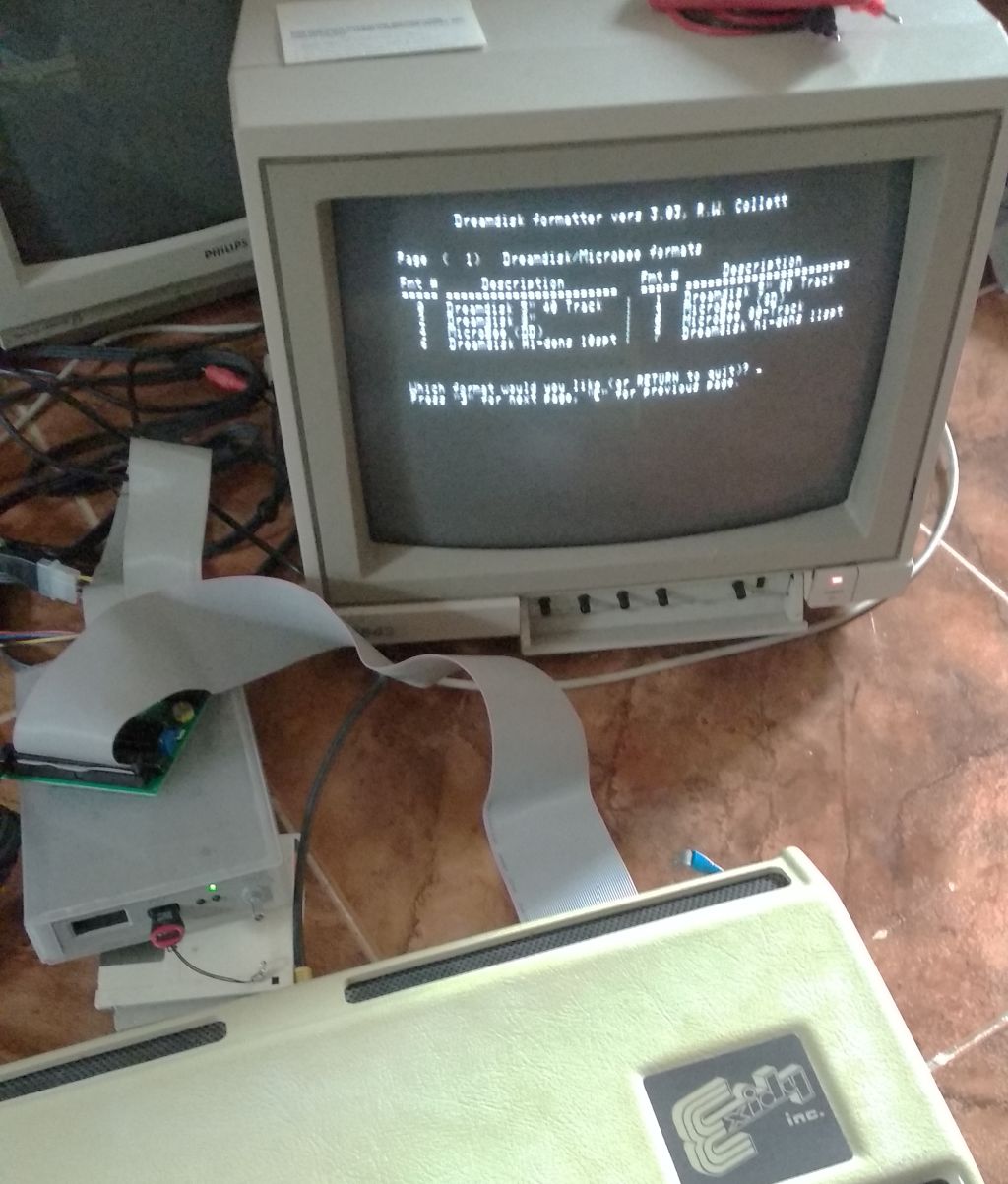
- Dreamdisk.jpg (139.27 KiB) Viewed 151012 times
I'm sorry for the bad quality photo; but my hands were shaking

Not too much tested until now. Machine boots; but not all .COM files work; so I need to spend some more time with it. I want a proper case with a single power source for both FDC and Gotek and a shorter expansion cable.
My main problem has been my heavily modded Sorcerer, I'm going to open a new [url=
https://www.exidysorcerer.net/index.htm ... p76}thread[/url] about it, maybe someone can shed some light about what's exactly inside my computer.
Now, I can share some knowledge about all of this so feel free to ask...
Re: Dreamdisk lives!
Posted: Sun Mar 24, 2024 9:10 pm
by johnhalk
Hello Jltursan !
Congratulations on your achievement - I am very happy its working for you !
Could you please share some tips which other Dreamdisk builders could also use ?
- How did you install the Scuamon 3.4 EPROMS (Did you do the PCB mod on the sorcerer motherboard or did you lift the PIN on the 2716 and jumper to +5v) ?
- Did you need to jumper the NMI trace on the Sorcerer 50 pin edge connector (per the Dreamdisk V2 manual) ?
- How did you perform the alignment on the Dreamdisk controller? (as much detail as possible).
- How did you configure the gotek drive with the Dreamdisk Image i.e. Flashfloppy configuration etc ?
I also use the MAME emulator with Dreamdisk FDC support to test the working of the dreamdisk images.
Regards,
John Halk
Re: Dreamdisk lives!
Posted: Mon Mar 25, 2024 8:32 am
by jltursan
- How did you install the Scuamon 3.4 EPROMS (Did you do the PCB mod on the sorcerer motherboard or did you lift the PIN on the 2716 and jumper to +5v) ?
No mod needed as my Sorcerer has a special interface that already uses a 2732 (as 1E) EPROM and another one in the Sorcerer motherboard. This allows for 8KB ROM shared between monitor 1.3b and monitor 1.0. One of my problems has been to replace these EPROMs with the right "combo" between halves of SCUAMON and monitor 1.0. Also, I needed to patch some 2764 EPROMs as I didn't have 2732 in my stack.
Did you need to jumper the NMI trace on the Sorcerer 50 pin edge connector (per the Dreamdisk V2 manual) ?
Yes, my Sorcerer needed a little wire between the expansion pin 6 and its nearest pad.
How did you perform the alignment on the Dreamdisk controller? (as much detail as possible).
1) Connect all, cables and power to FDC and floppy
2) Check test jumper JP1 is open
3) Turn on FDC and floppy
4) Turn on Sorcerer
5) Close test jumper
6) Using an oscilloscope and turning R5, try to get a pulse of 500ns measured over TG43. Ground can be easily found in the right leg of D1 (closest to U6)
7) Now, measuring over DIRC and turning C4, try to get a frequency of 250Khz.
8) Close test jumper and restart all again.
How did you configure the gotek drive with the Dreamdisk Image i.e. Flashfloppy configuration etc ?
No configuration needed. Saved the dsk files in a pendrive and selected the masterdisk to boot right after the Sorcerer is turned on.
Re: Dreamdisk lives!
Posted: Mon Mar 25, 2024 9:12 am
by johnhalk
Thanks for the information - it will be very useful to other Dreamdisk builders.
With your Gotek are you using the standard gotek firmware or have you installed flashfloppy firmware or HXC floppy firmware ?
https://github.com/keirf/flashfloppy
https://hxc2001.com/docs/gotek-floppy-e ... -firmware/
Regards,
John
Re: Dreamdisk lives!
Posted: Mon Mar 25, 2024 12:41 pm
by jltursan
This Gotek uses a plain FlashFloppy 3.x firmware, probably not too old...
Now I need to discover how to create blank Dreamdisk compatible images (40 or 80 tracks) and how to inject files into them. Maybe using 22DISK?
Re: Dreamdisk lives!
Posted: Sun Jul 14, 2024 10:30 am
by jltursan
Just a little update to show what's probably my final Dreamdisk unit:
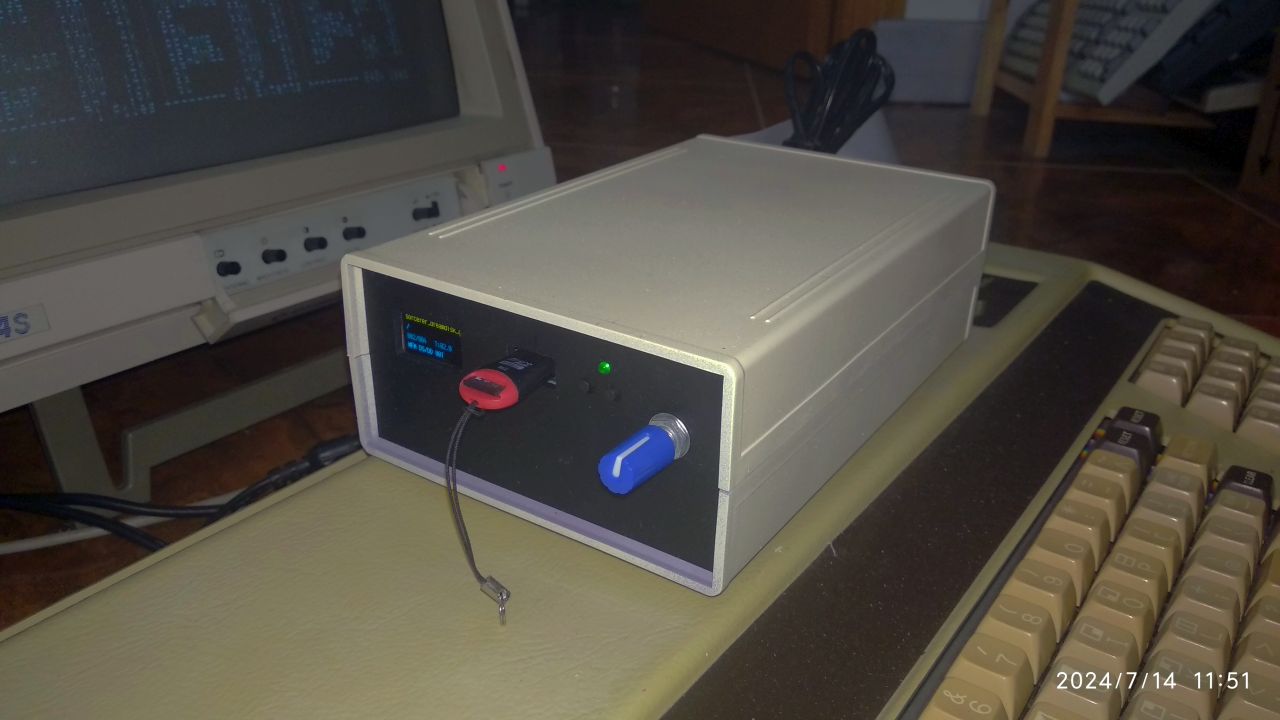
- Exidy_Dreamdisk.jpg (81.8 KiB) Viewed 150364 times
A prototype case, some creamy and black spray painting and a lot of sawing did the trick. It's powered with a 5V PSU and has its own rocker switch.
Maybe, if I find a way, I'll add some "Exidy" vynil in the front fascia. As for now I'm very happy with the result

Re: Dreamdisk lives!
Posted: Tue Jul 16, 2024 1:58 am
by johnhalk
Hi Jltrusan,
That looks really nice and well finished. Maybe you could build a few Dreamdisk units and sell on EBay ?

Have you been able to put together some Dreamdisk CP/M images using cpmtools ?
Regards,
John Halk
Re: Dreamdisk lives!
Posted: Wed Jul 17, 2024 4:43 pm
by jltursan
Hahaha, it took me weeks!. I'm moderately skilled in electronics; but extremely clumsy with any kind of handwork. Anyhow, I can post here the box I've used, purchased in Aliexpress:
https://es.aliexpress.com/item/10050056 ... pt=glo2esp
The controller and the Gotek stacked on top of it, fit really well inside the case
Have you been able to put together some Dreamdisk CP/M images using cpmtools ?
Yep, following ChickenMan's instructions in
this thread I was able to edit existing images, or at least, add software to them. Soon I'll need to create new images from scratch as I've plans to use disks as the main media when creating games with my port of
MPAGD to the Sorcerer.
Are any of you interested in "easily" programming games for the Sorcerer?. Right now, I'm testing the engine only with this game prototype:
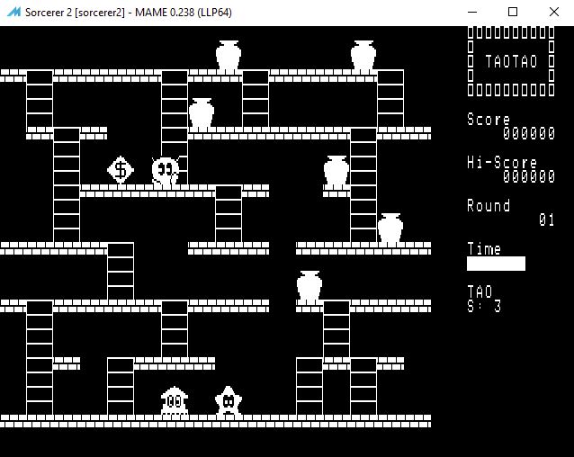
- TaoTao.jpg (53.72 KiB) Viewed 150351 times
Re: Dreamdisk lives!
Posted: Sat Mar 08, 2025 3:27 am
by johnhalk
Dreamdisk floppy disk controller build underway by VectorXY. Dreamdisk Floppy disk Controllers may become available pre-built and tested.
Watch here for updates.
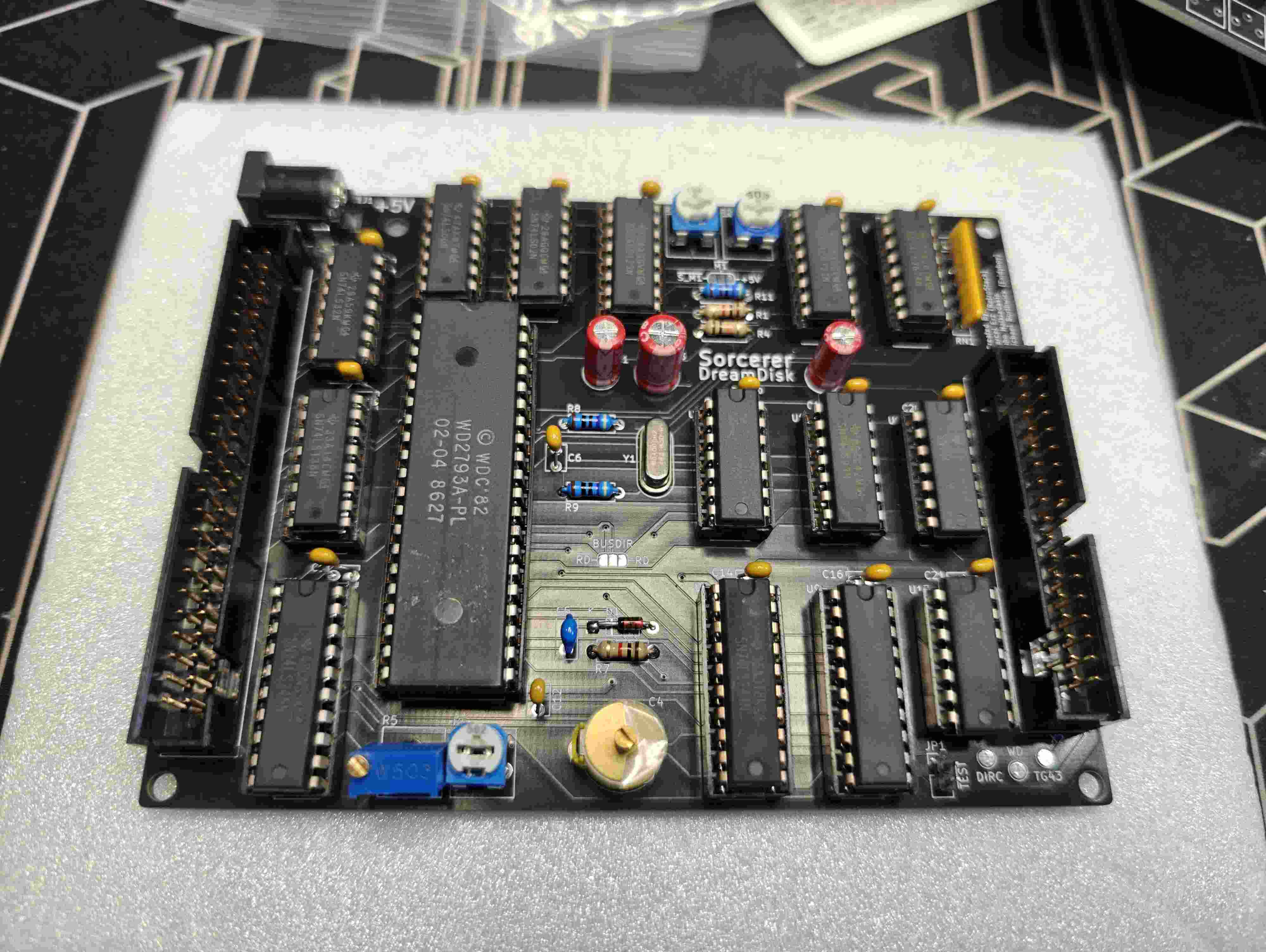
- IMG20250307121244.jpeg (222.02 KiB) Viewed 108257 times
Re: Dreamdisk lives!
Posted: Wed Mar 12, 2025 11:24 pm
by johnhalk
Hi All,
It appears we have a small bug in the testing/documentation for the dreamdisk - it will read OK from floppy disk/image but it will not write data to a floppy disk/image.
We are doing some more testing with the BUSDIR test jumper on the dreamdisk PCB - that's why the jumper is there on the PCB - to test various scenarios for the BUSDIR signal. It appears that we just need to leave all the BUSDIR test pads un-jumpered.
More information to follow once we do some more testing.
Regards,
John
