trying to assemble the floppy disk controller
Posted: Tue May 14, 2024 8:00 pm
HI, last week I finally assembled the Floppy disk controller (R7 is now mounted, I did the pic before, as I missed this component)
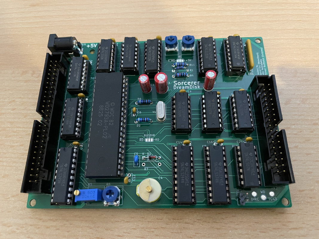
But something is not right: my friend took his oscilloscope and we tried to adjust both potentiometers, but nothing change. We have even a very strange ripple signal:
https://imgur.com/a/f8Mcpsl
Then we checked the voltage between TG43 and the ground, and we have 2.3V... We checked the board for short circuit, it looks good.
Any idea what can be the cause?
Thanks